This guide will walk you through the process of assembling the arms for your Maslow 4.1 CNC. The arms are a critical component that house the belt system, encoders, and motors that control the machine’s movement.
Tools and Parts Needed
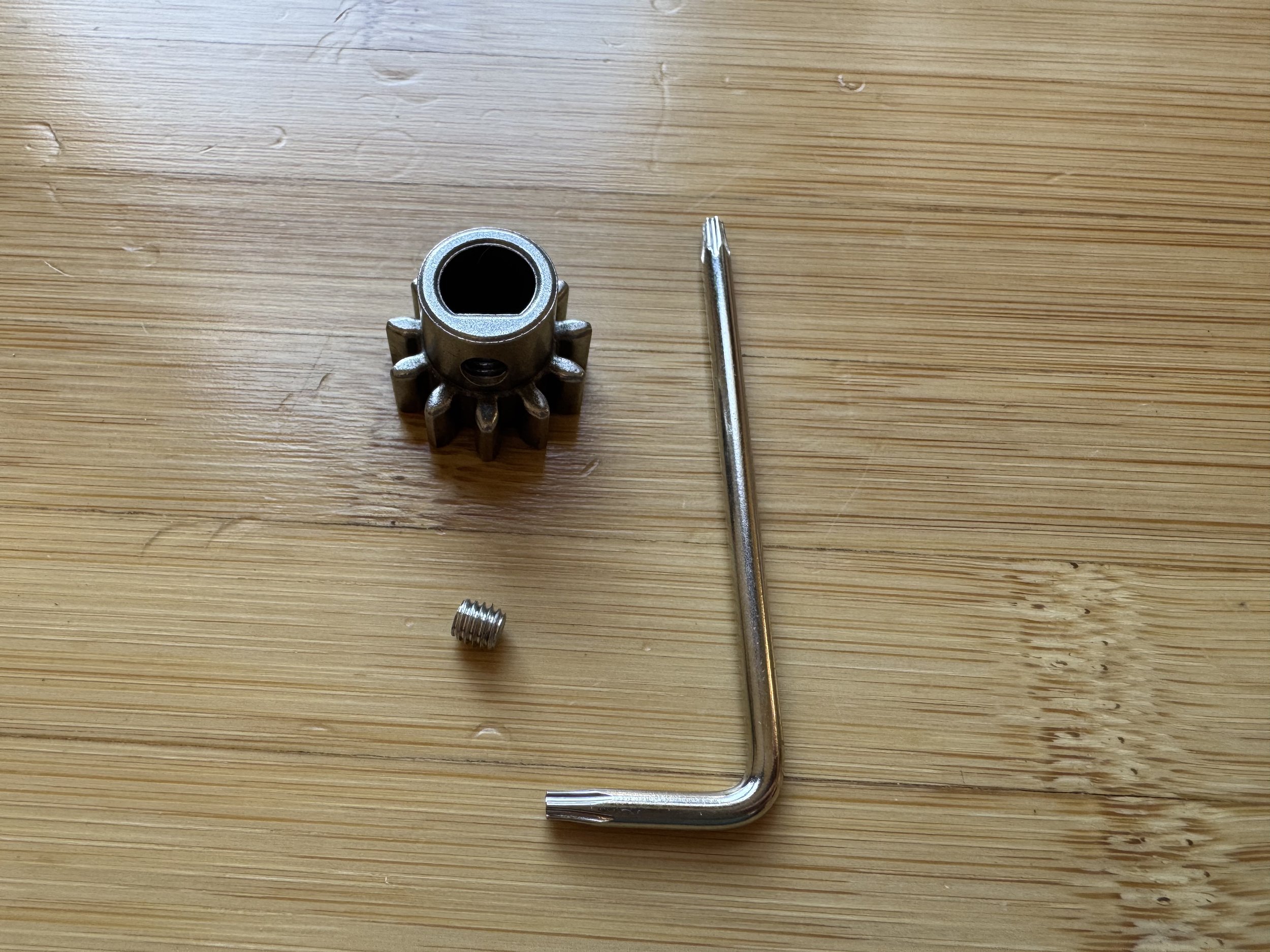
- Allen wrench or T10 Torx screwdriver
- Four belts
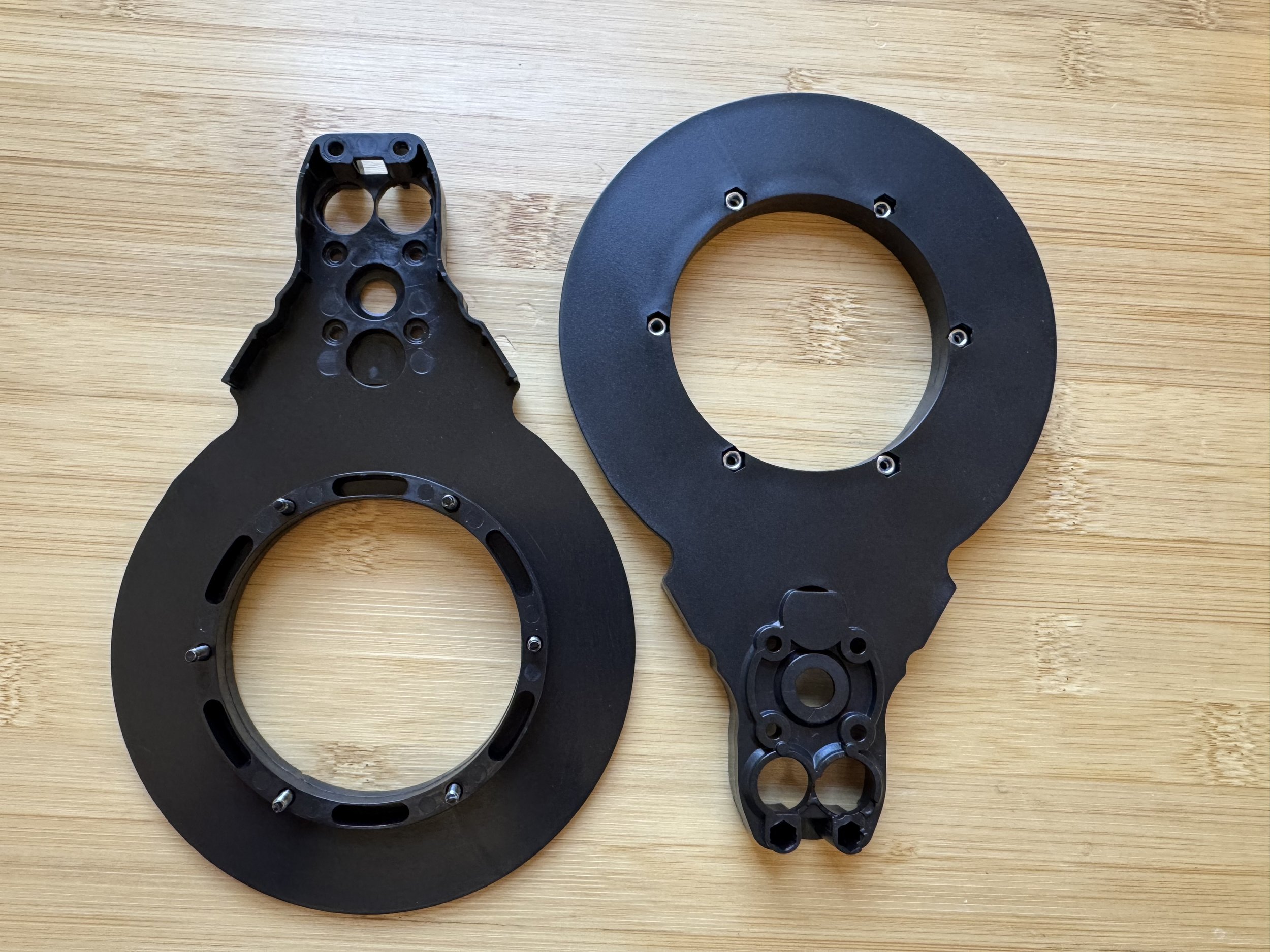
- Four arm halves (top/bottom are identical)
- Eight rollers
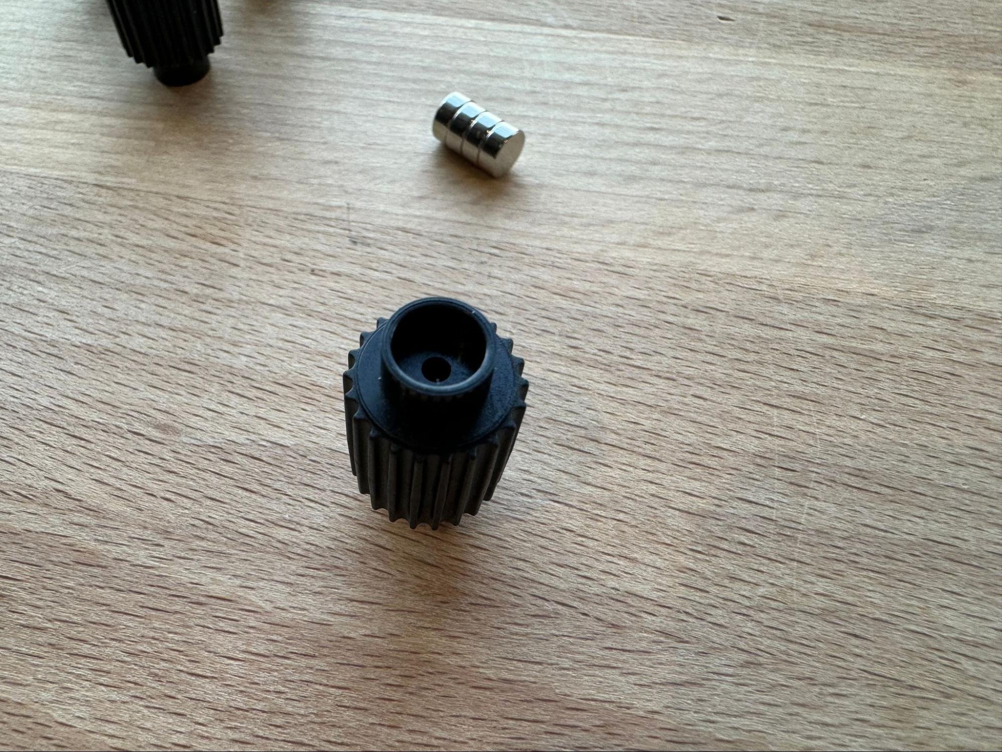
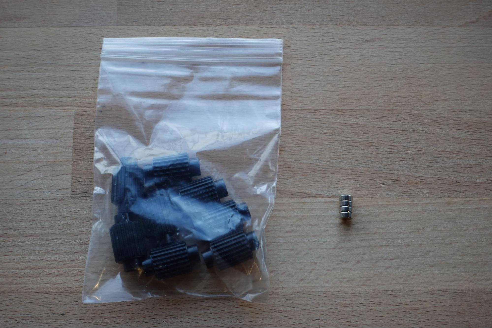
- Four encoder board magnets
- DC drive motor
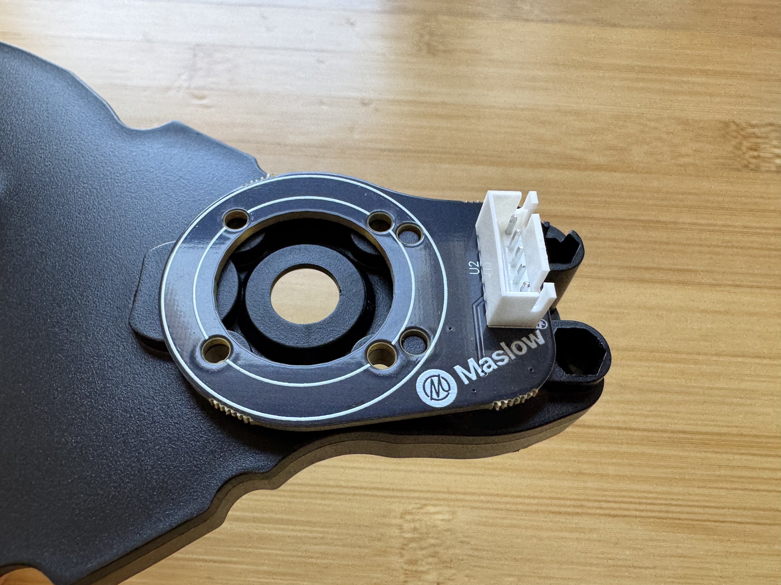
- Encoder board
- Bolts (without threadlocker)
- Locking nuts
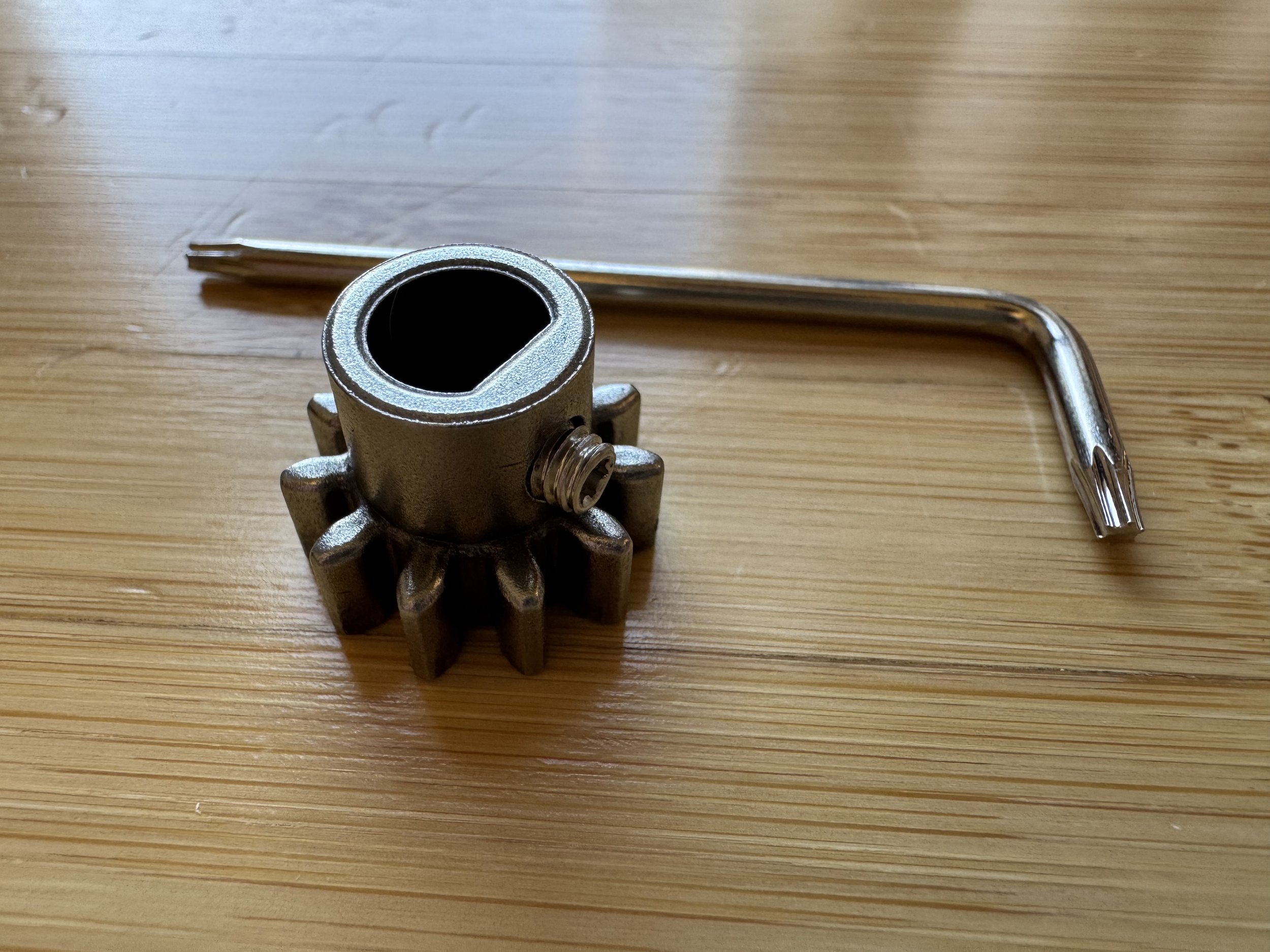
- Drive gear, idler gear, bearings, belt guards
- Super glue (for non-structural vibration protection)
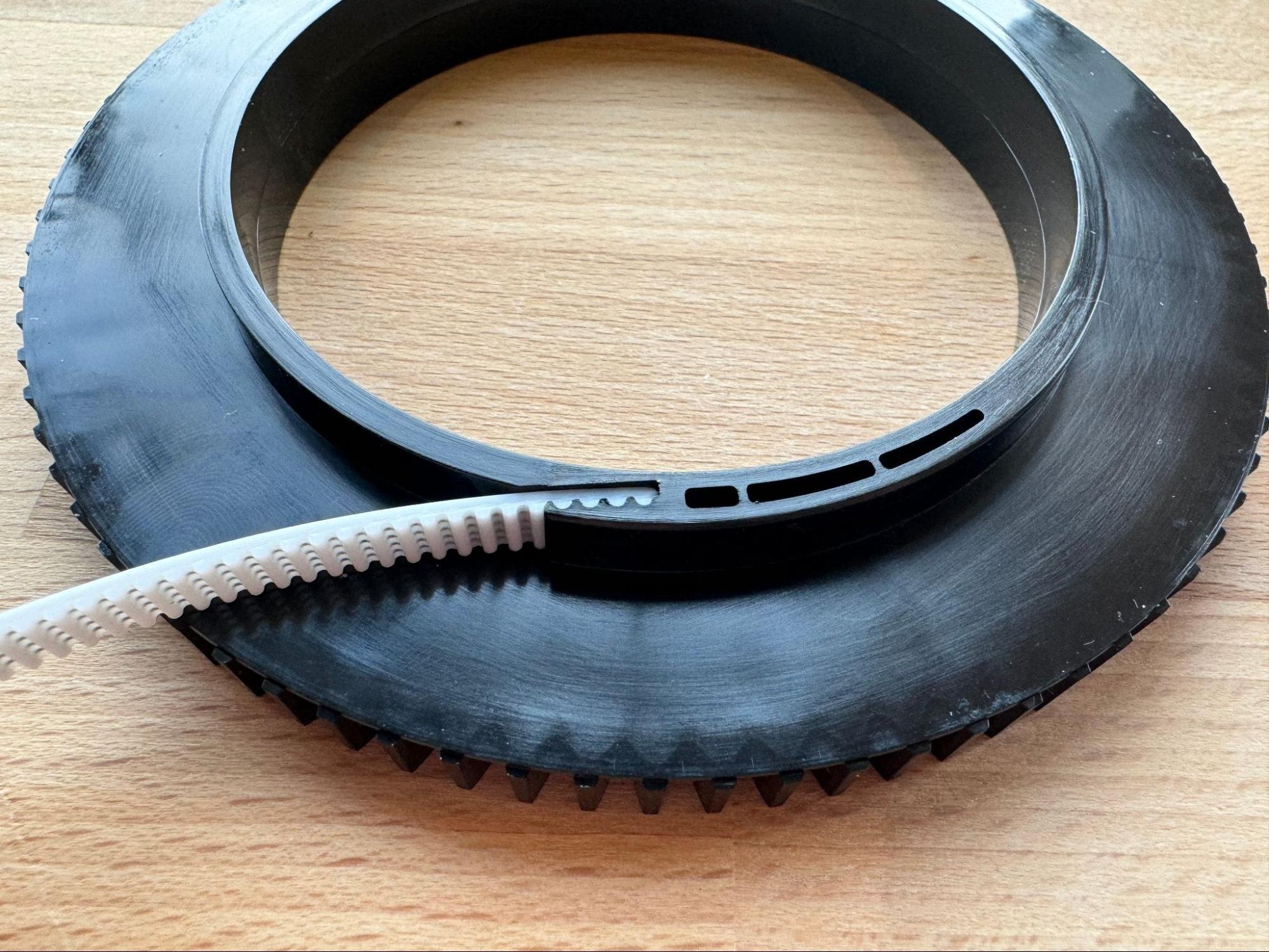
Step 1: Glue Belt Ends to Spools
Remove the spool from each arm. Add a small drop of super glue to the slot for the belt end. Insert the belt fully so it sits flush. Repeat for all four spools.
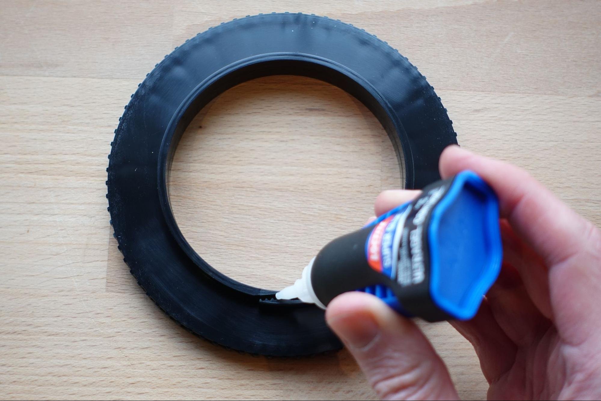
Tip: Some kits may arrive with these pre-glued from the factory. Check yours before adding additional glue.
Tip: Sometimes one end of the belt fits more easily than the other. Check both before gluing.
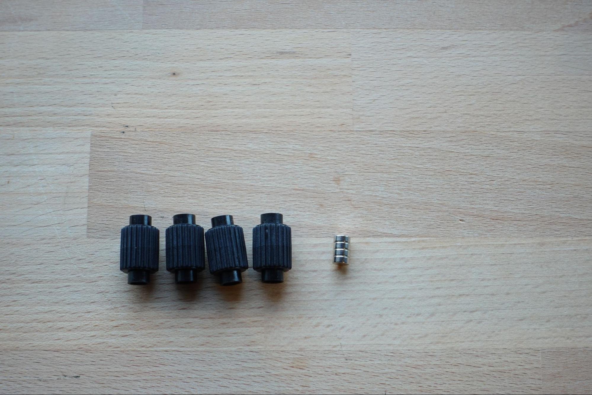
Step 2: Install Encoder Magnets
Each roller has a shallow recess where the magnet goes. Use a small drop of glue to place a magnet in this recess. The magnet should be recessed below the roller top.
Important: Keep rollers separated until glue sets, as the magnets may attract each other. The orientation of the magnet doesn’t matter.
Step 3: Install Bolts and Nuts in Arm Halves
In one arm half, insert six bolts (without blue threadlocker). Use a non-lock nut to pull them into place, then remove the nut after.
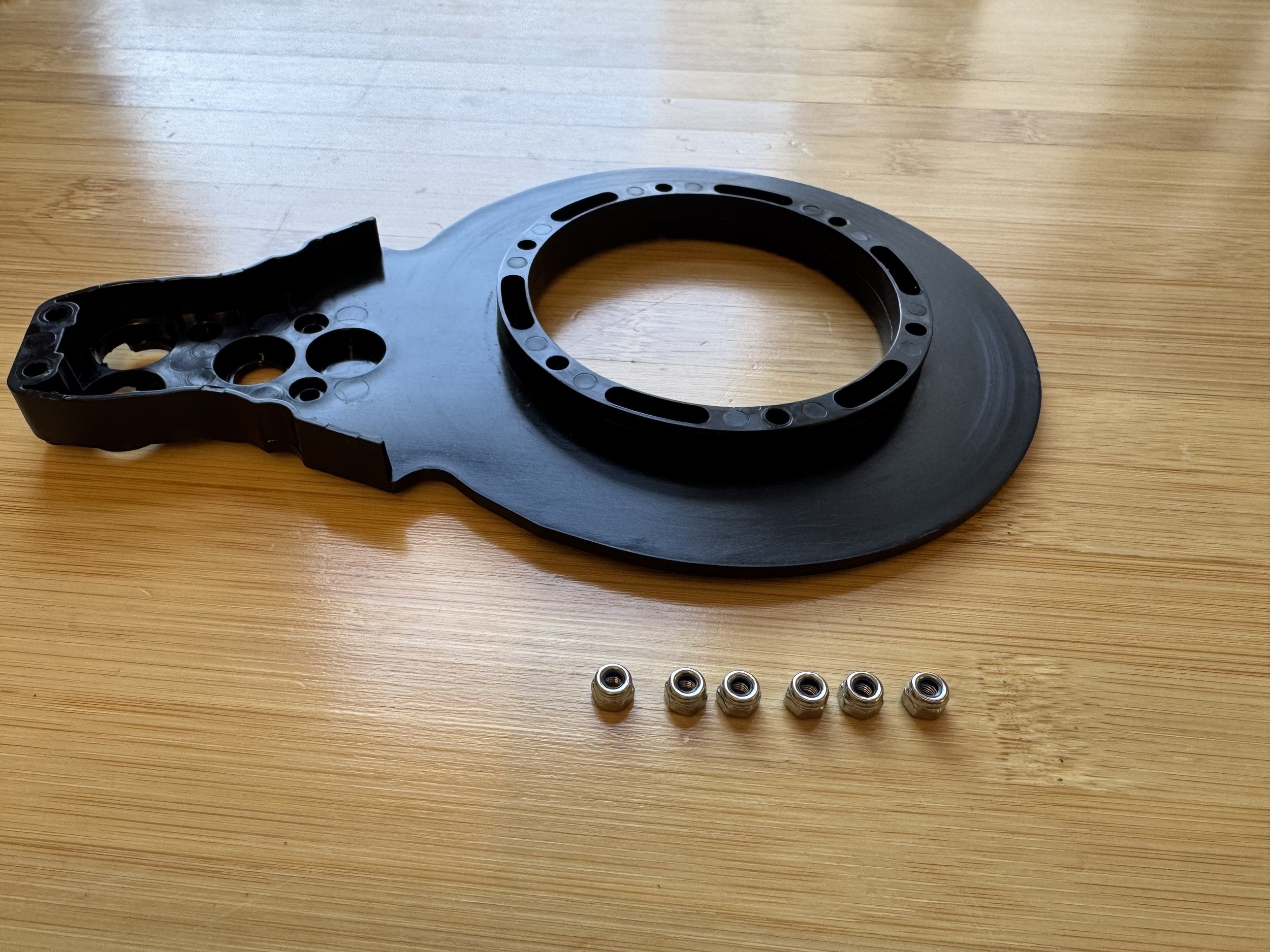
In the second arm half, insert locking nuts into the hex-shaped recesses. Use a bolt from the opposite side to pull each nut into place, then remove the bolt.
After this step, one arm half should have only bolts, and the other should have only nuts.
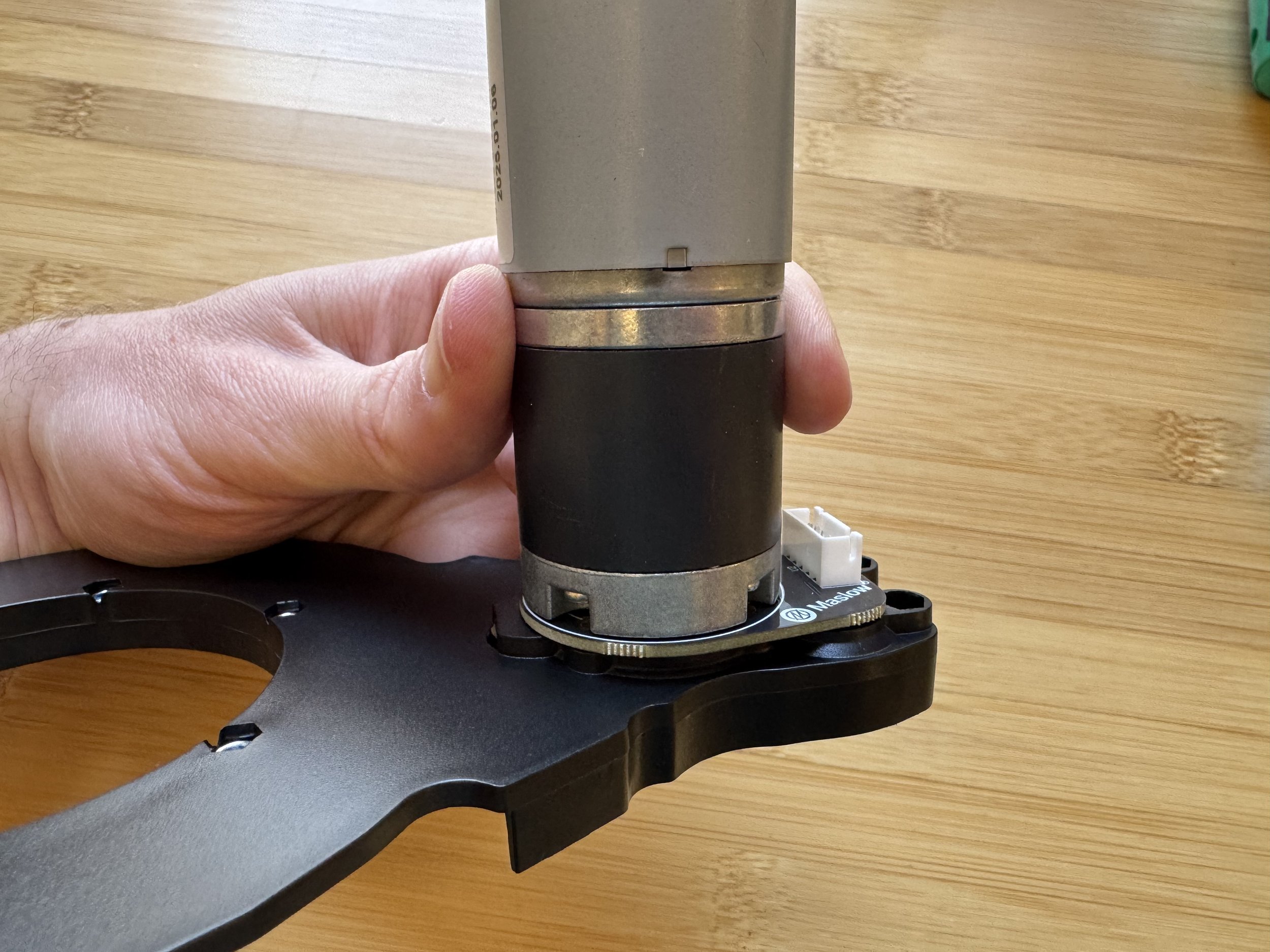
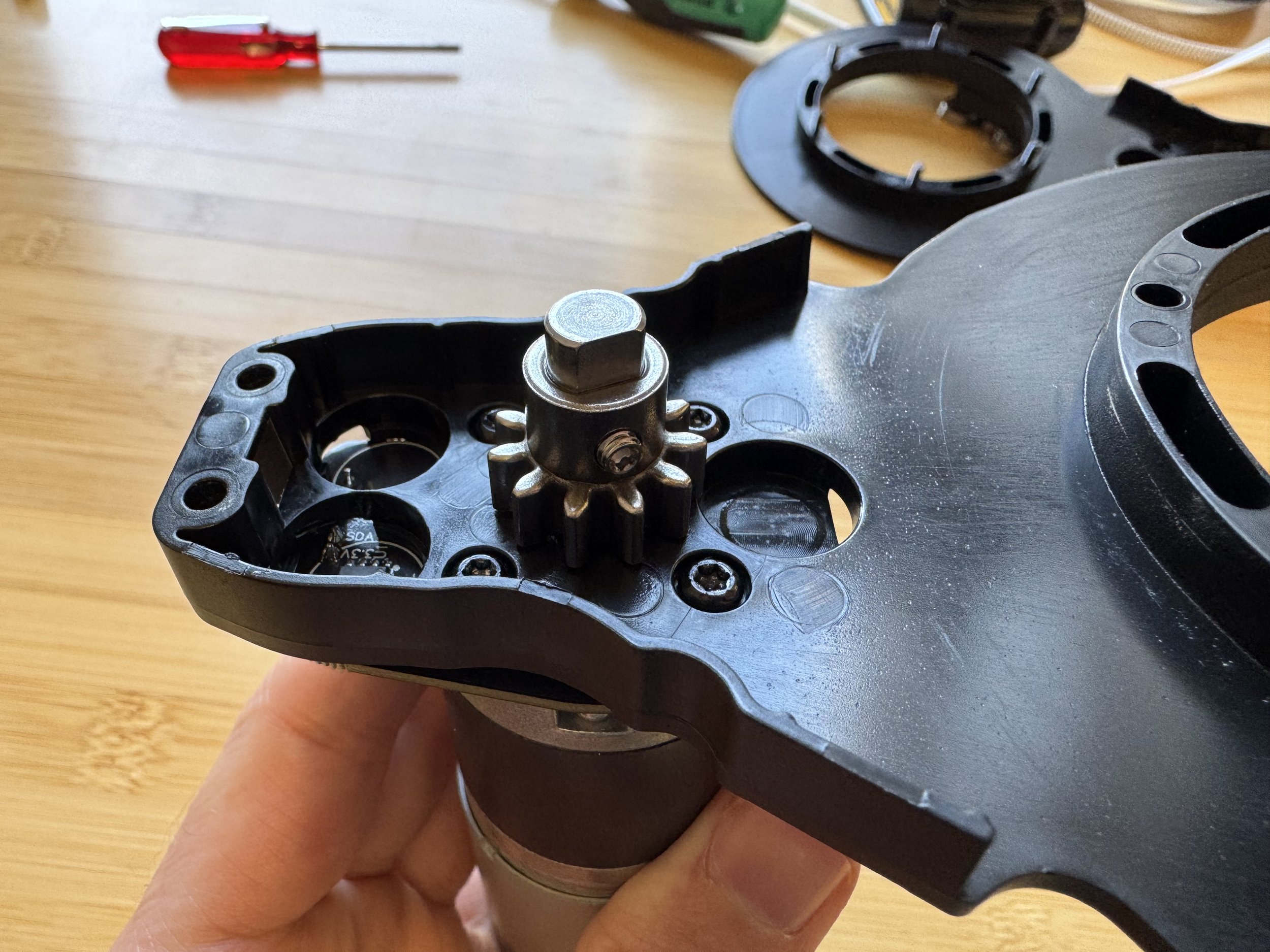
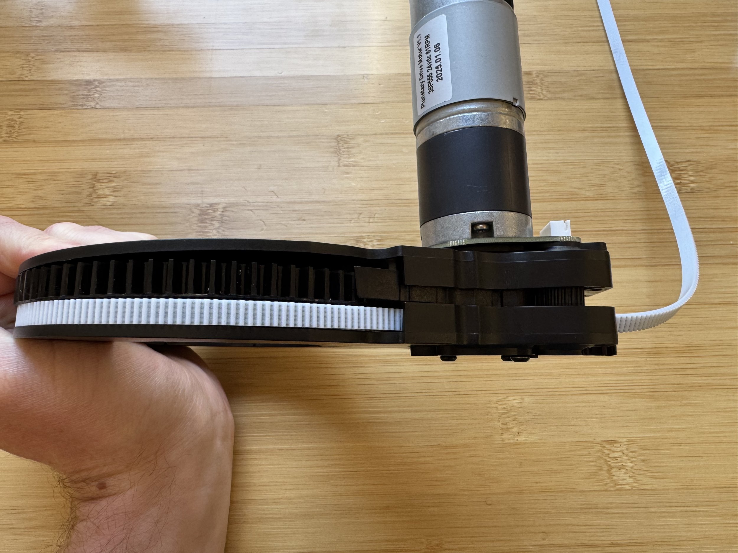
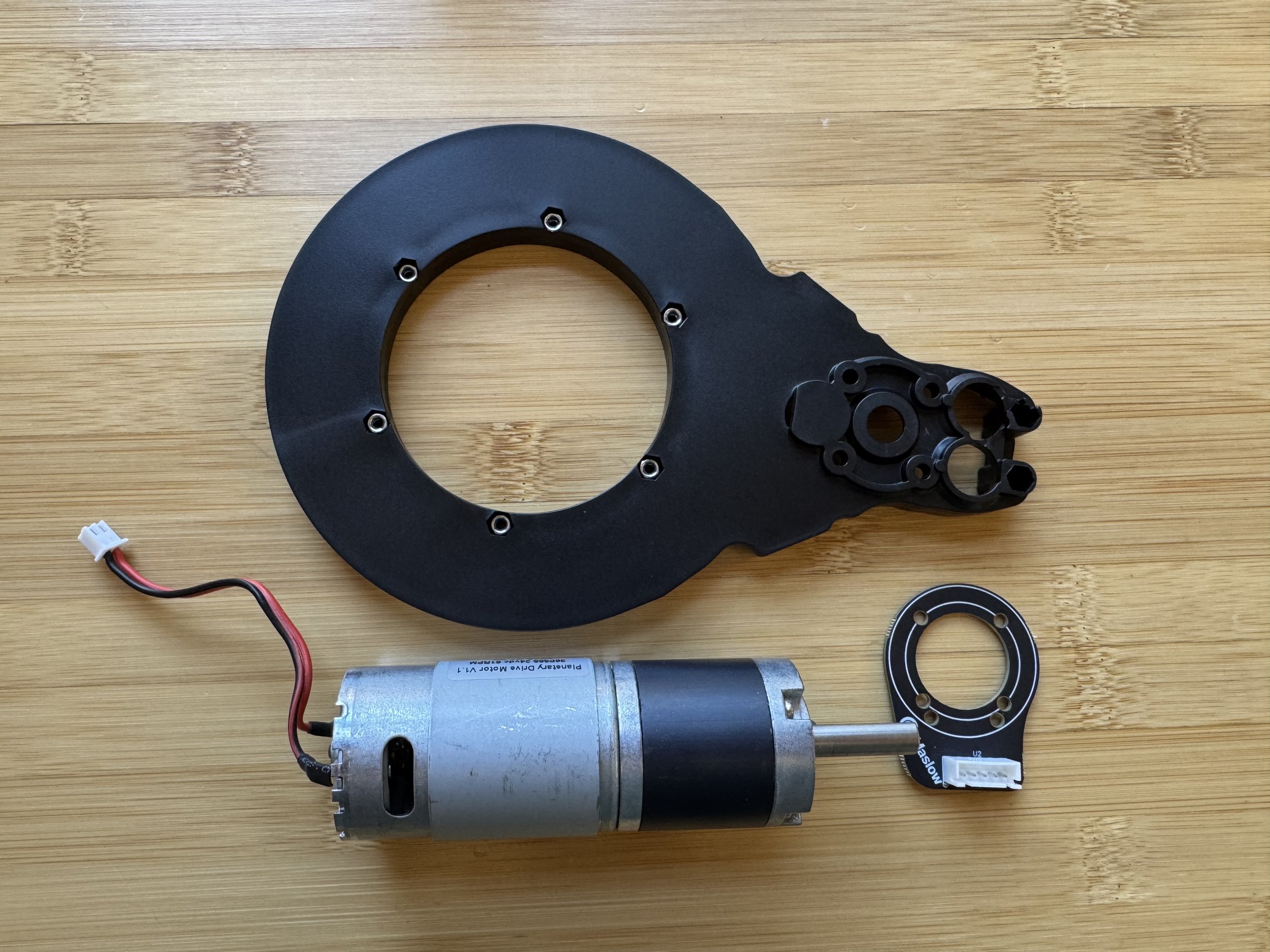
Step 4: Mount Encoder Board and Motor
Collect an arm half, a DC drive motor, and an encoder board.
Place the encoder board onto the arm half, aligning guide pegs.

Attach the DC drive motor over the encoder board. The orientation of the motor doesn’t matter.
The bolts which connect the motor to the arm can wiggle themselves loose over time so we’ve included bolts with blue removable threadlocker applied to them in your kit.
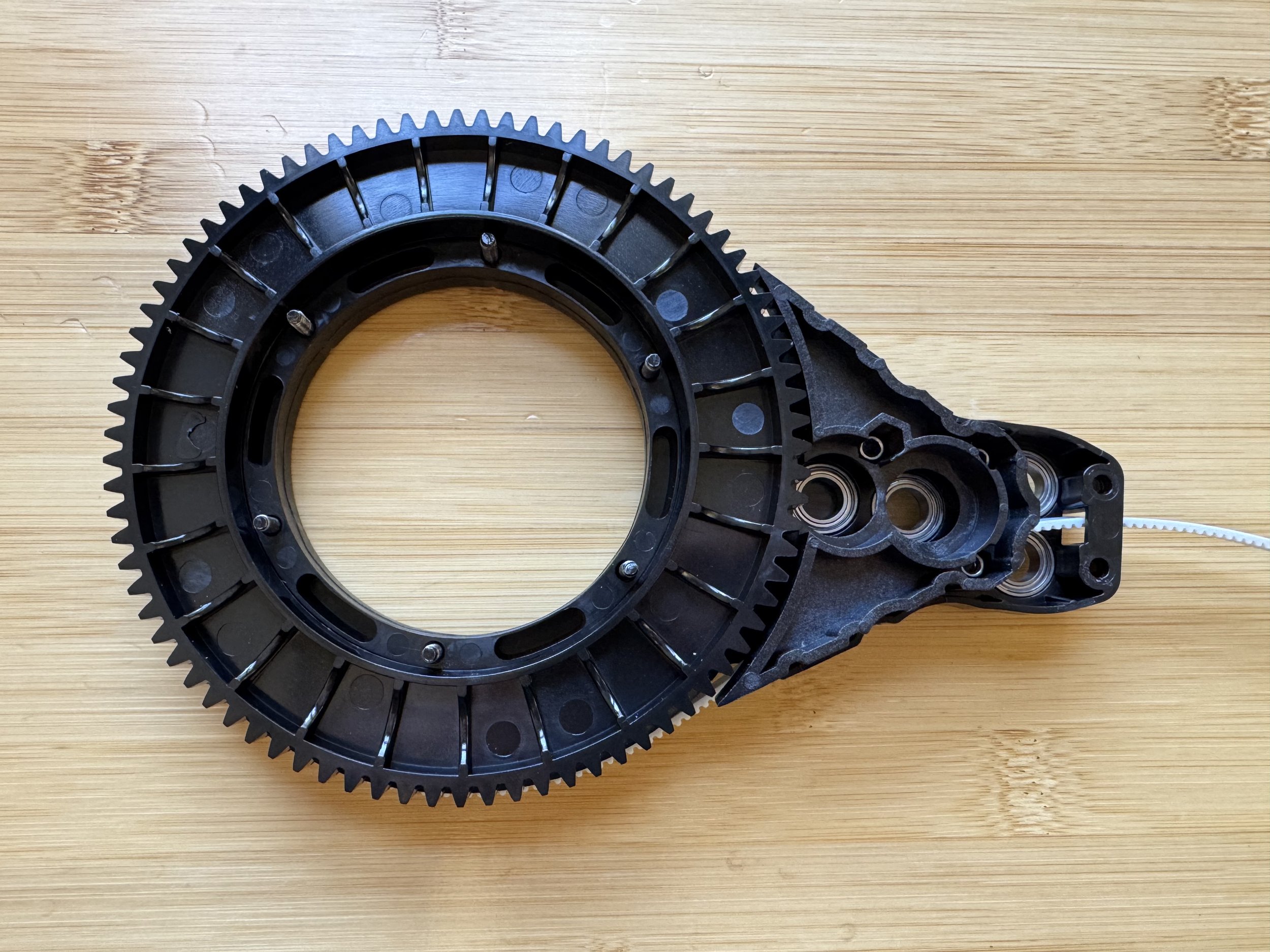
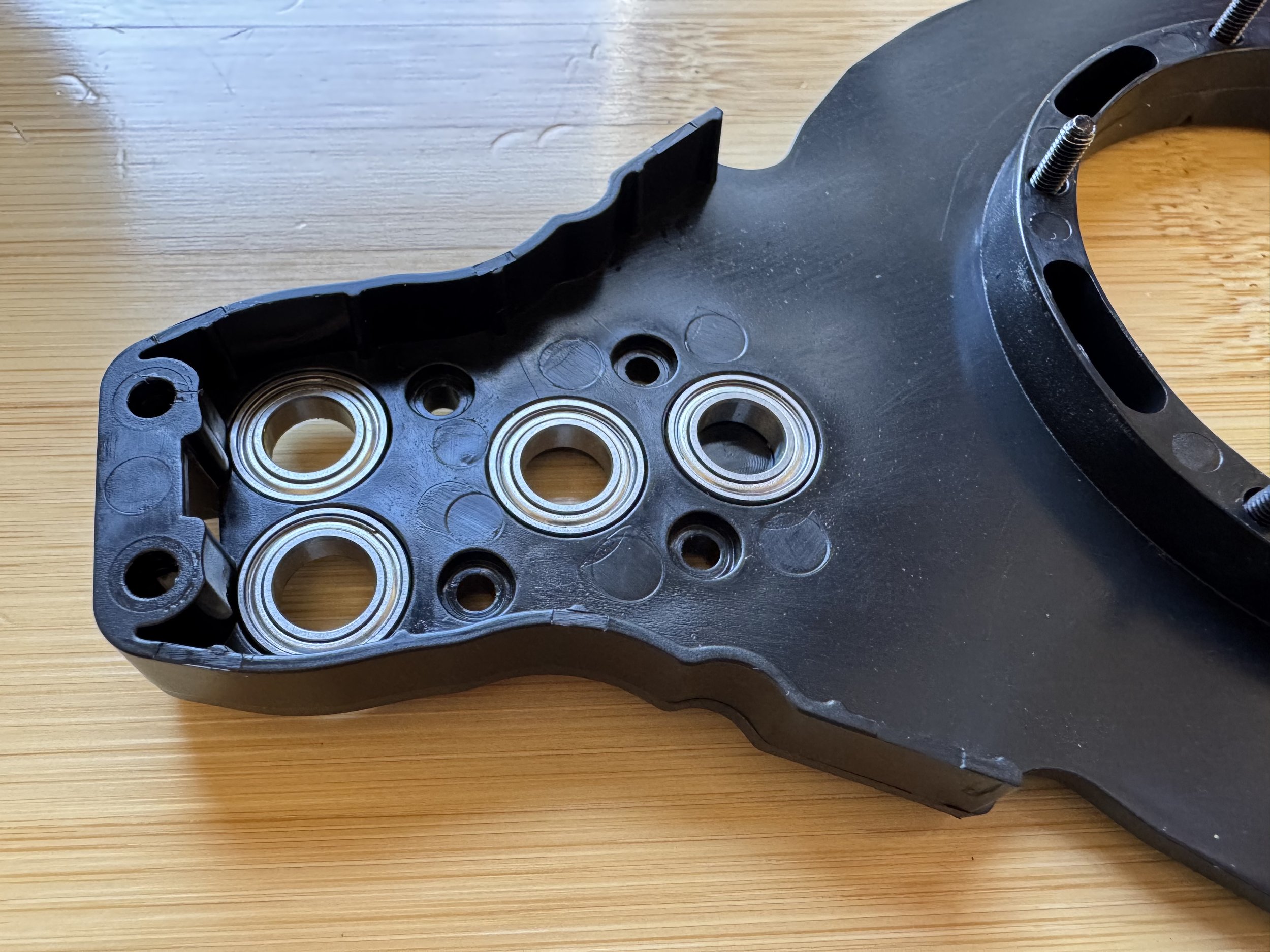
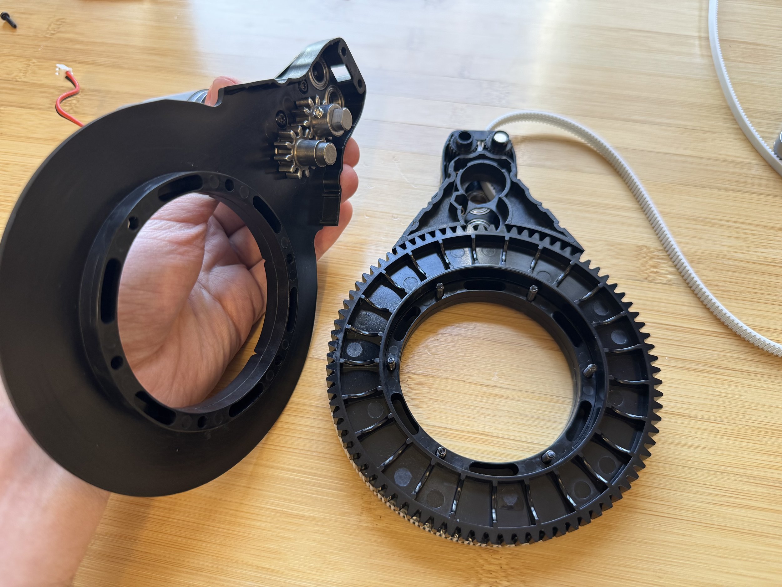
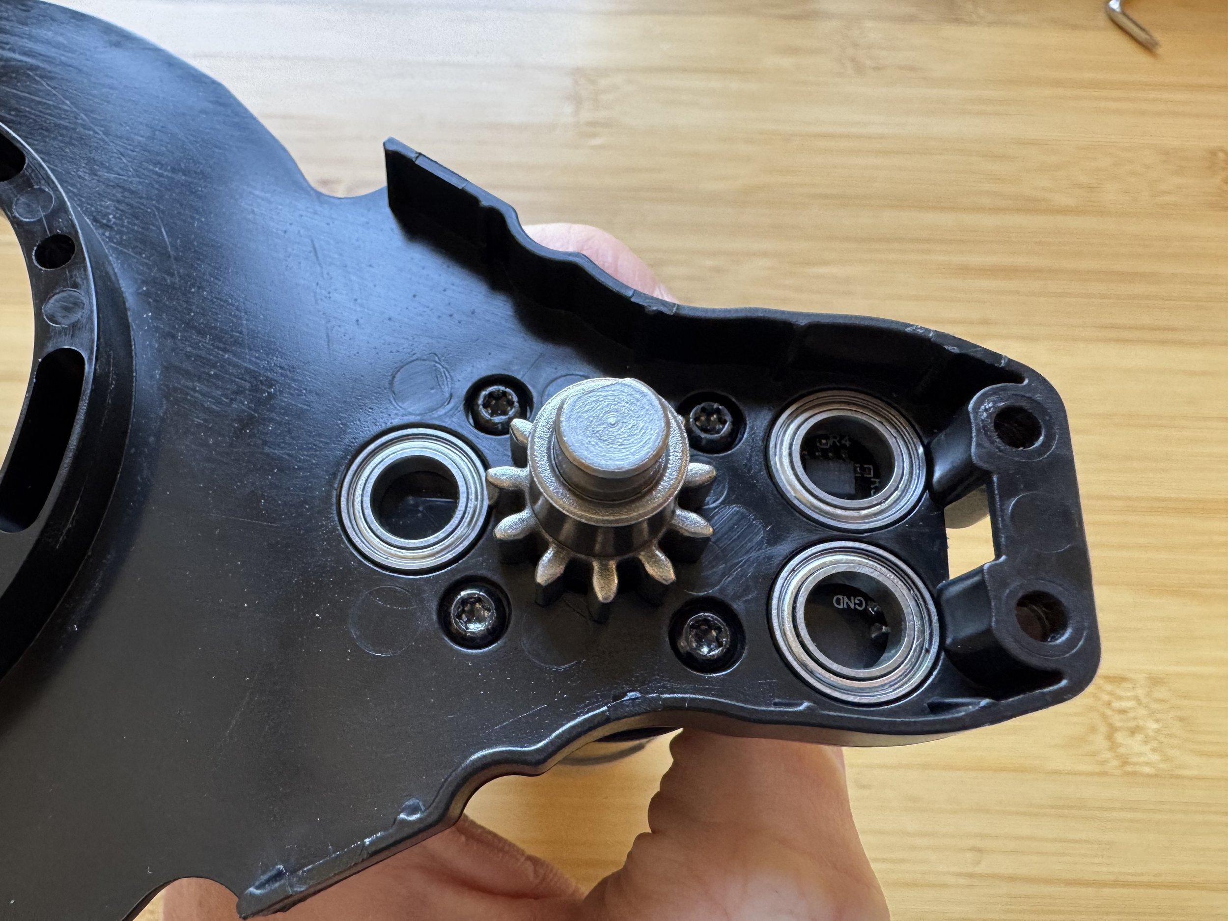
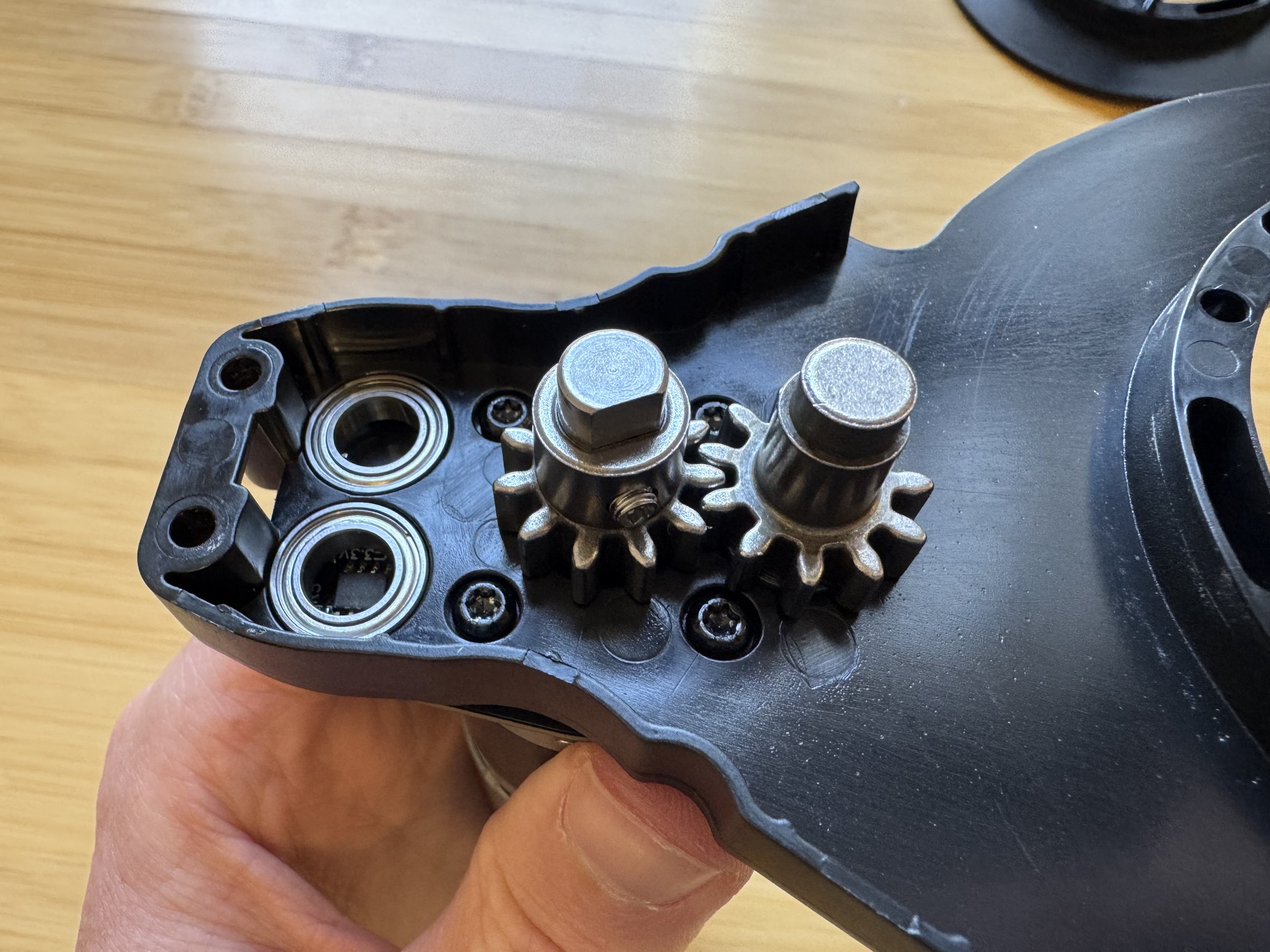
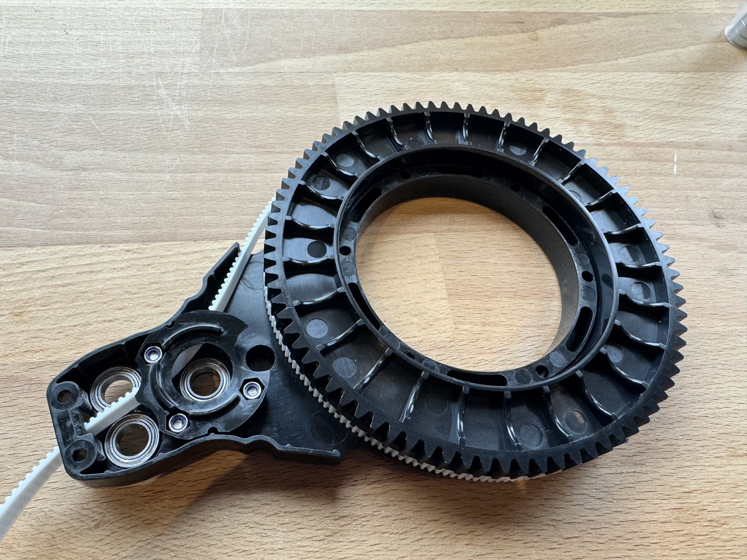
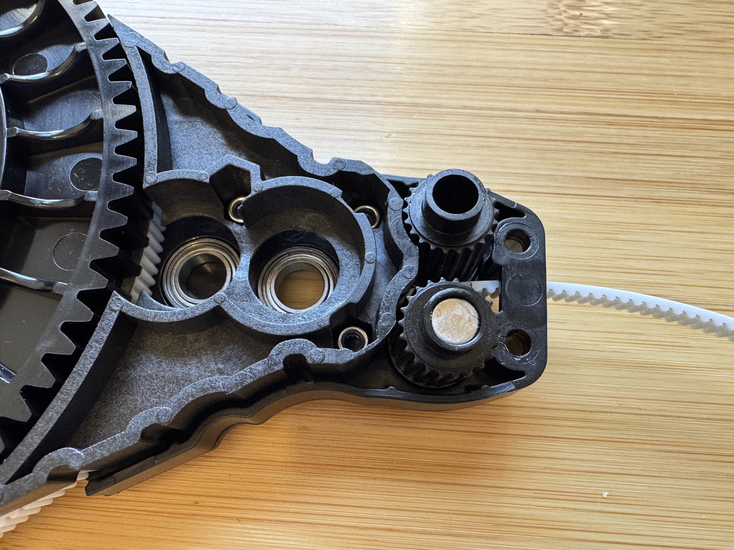
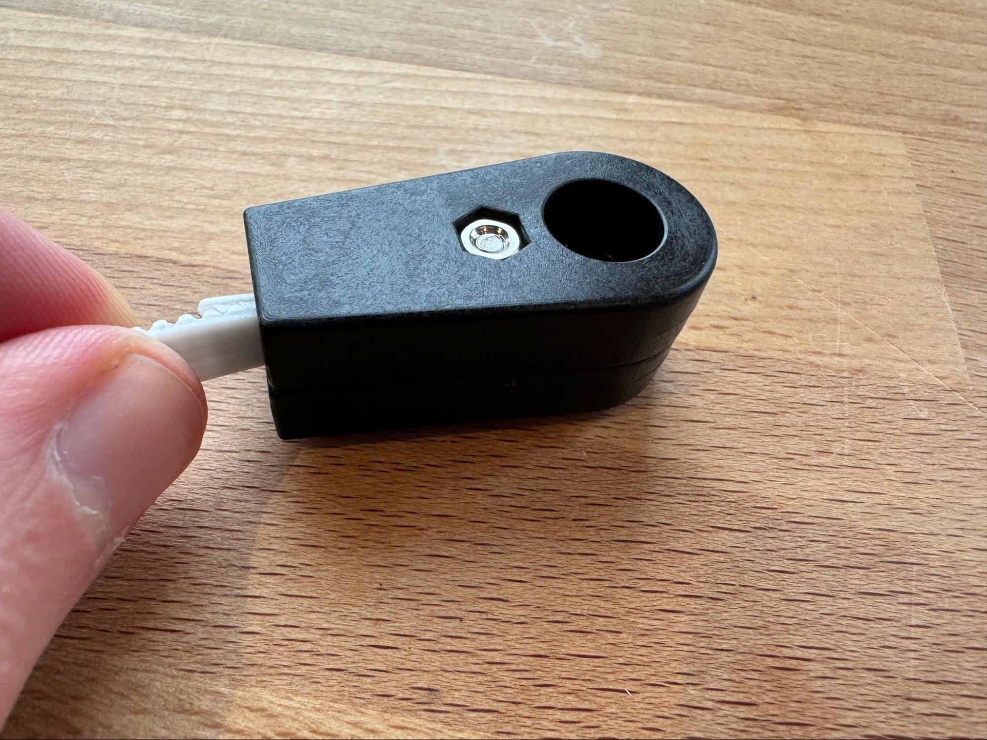
Step 5: Install Bearings, Drive Gear, and Belt Guard
Place three bearings and the drive gear on one side of the motor. On the opposite arm, install four bearings.

Attach the belt guard using three nuts and bolts from the back.
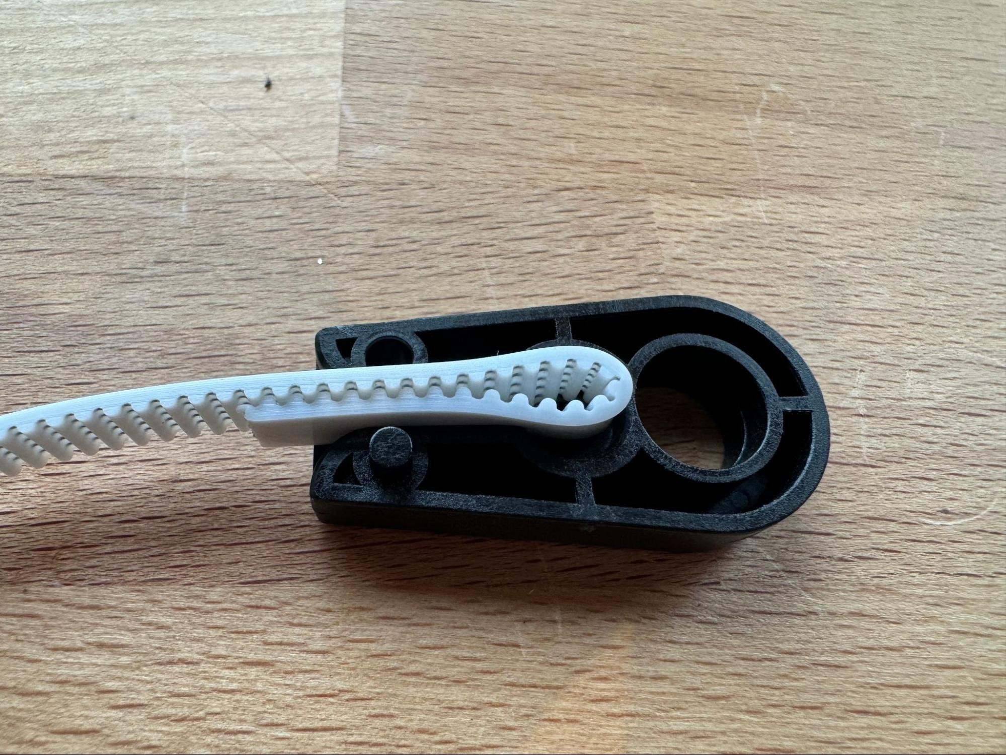
Step 6: Feed Belt and Install Spool
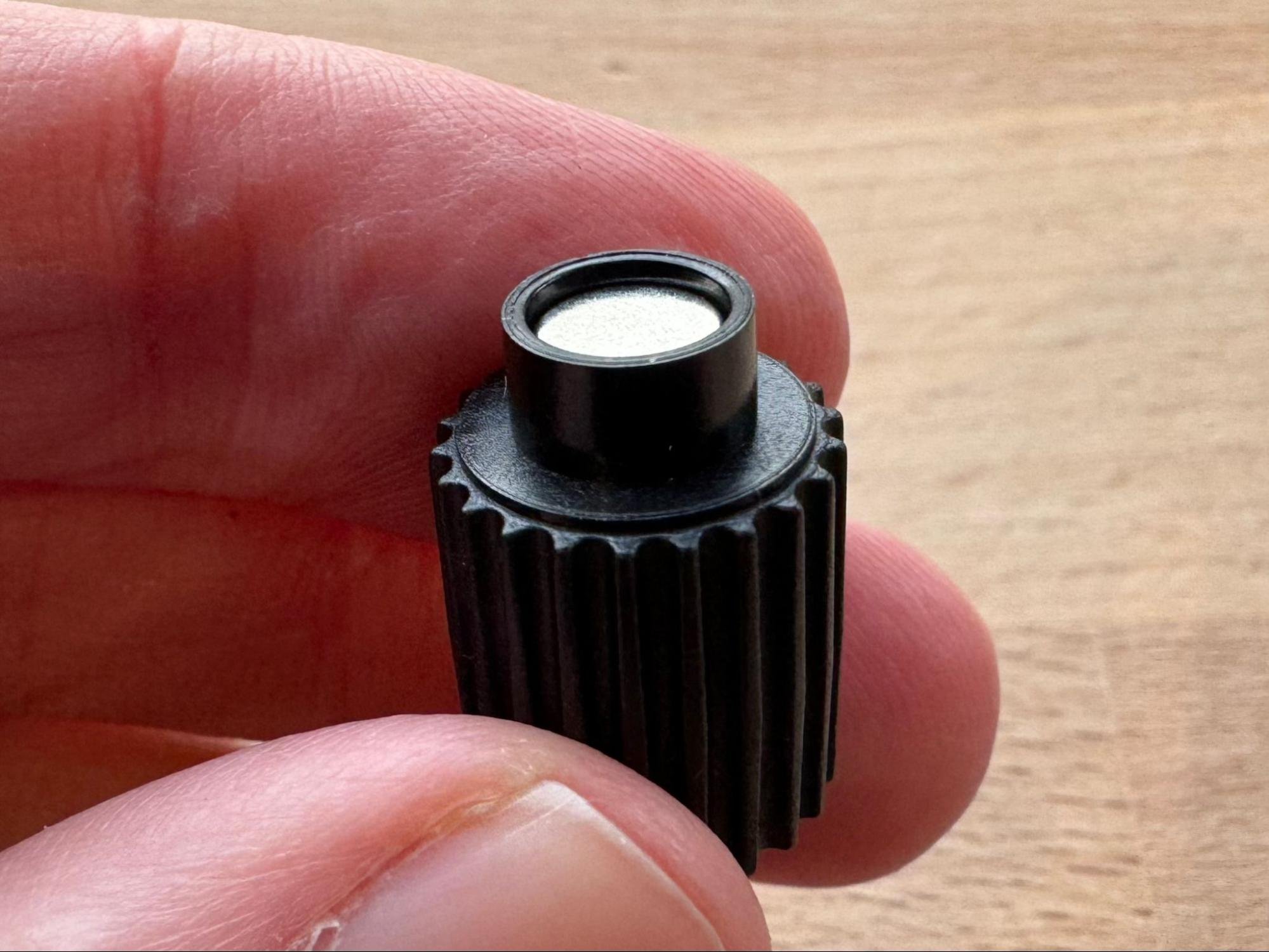
Feed the belt through the arm and install the spool. Place rollers, ensuring correct position of the magnet.

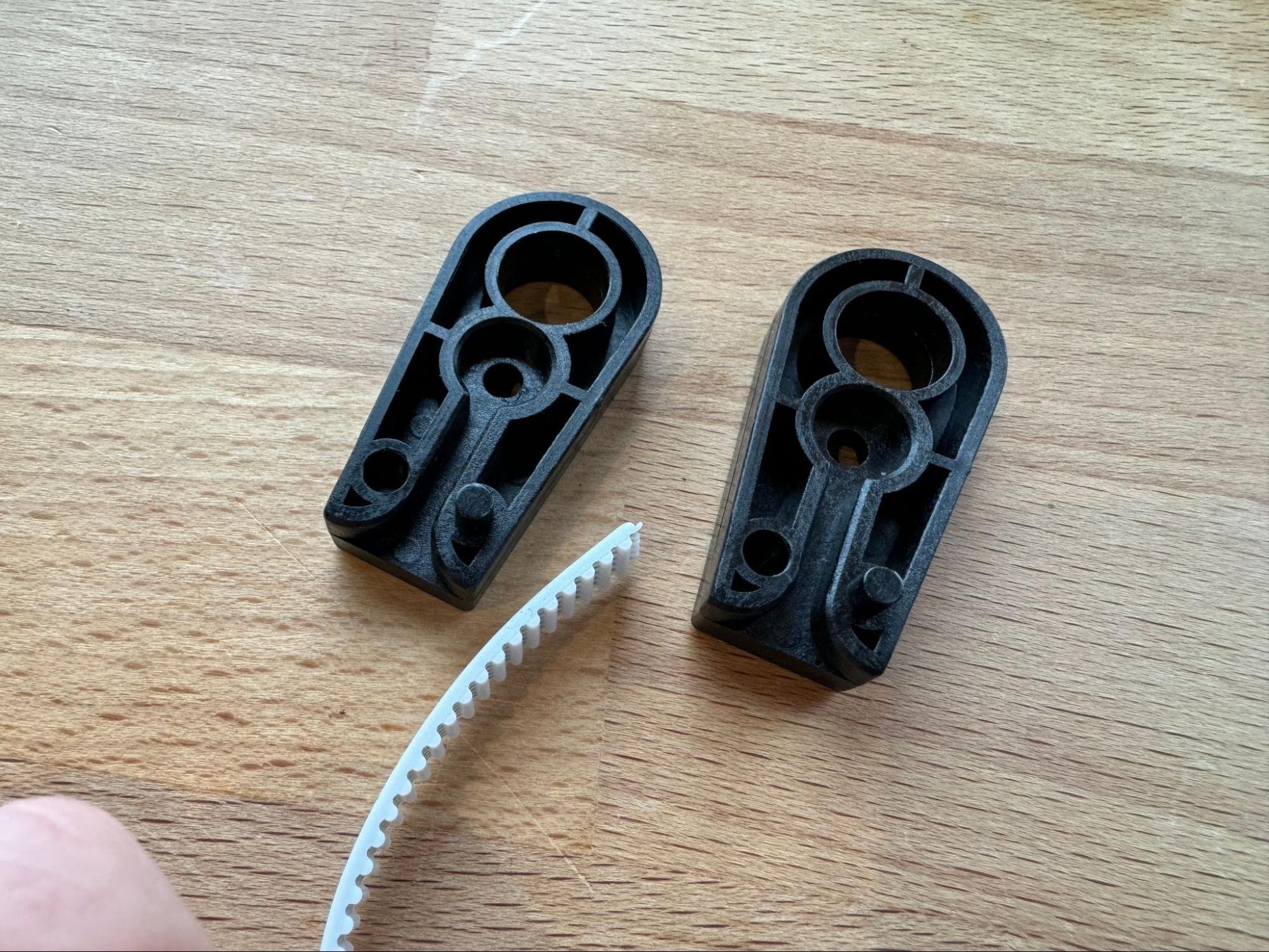
Step 7: Connect Arm Halves and Finish Assembly
Join the two arm halves using eight bolts. It may require some jiggling to align gears, rollers, and parts. Start at the back (furthest from the belt exit) and move forward, confirming alignment.
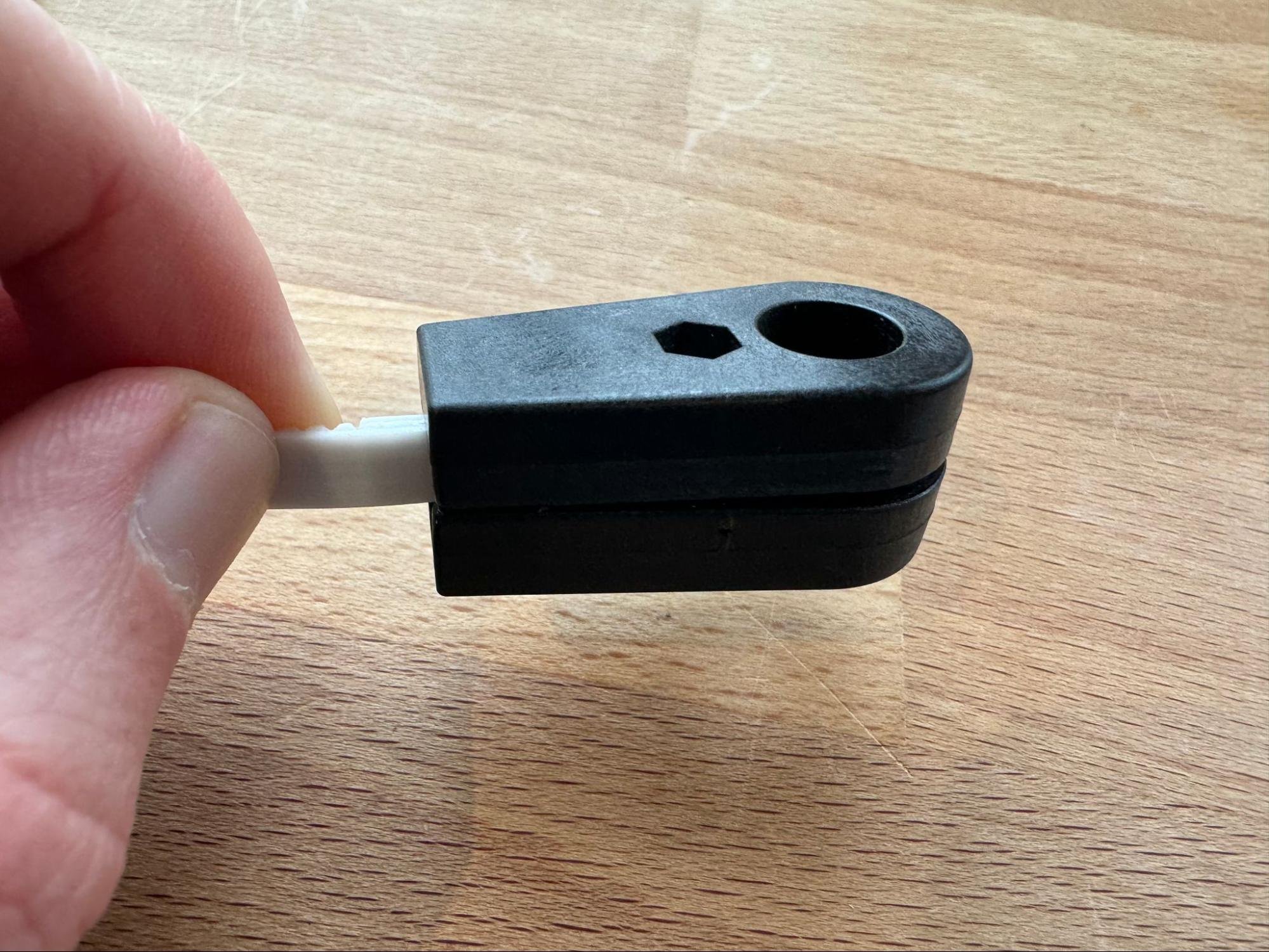
Connect the belt end to the belt. On the opposing arm, add the idler gear.
Repeat for All Four Arms
Each arm follows the same assembly steps. The belts, arms, and magnets form the core of Maslow 4’s tensegrity design.
Tips and Troubleshooting
- Use a T10 Torx screwdriver for most bolts; a T8 for setscrews holding gears to the motor.
- A drill with low torque can speed up bolt installation, but hand-tighten anything critical.
- There may be a small gap (1-4mm) between assembled arms—this is normal.
- For very tight bolts/nuts, a three-finger torque is generally sufficient.
- Be careful not to overtighten, especially on plastic parts.
- If the spool fits tightly, try sanding the inside of the spool or lightly polishing the screw heads.
Next Steps
Once all four arms are assembled, proceed to Assembling the Sled.